显示标签为“Printed Circuit Board”的博文。显示所有博文

2015年9月8日星期二

Semi-flexible PCB technology


With simple depth-milling a standard printed circuit board can be prepared for flexible installations. So called "semi-flexible" printed circuits are offering a cost-efficient solution. They save connectors and increase reliability while decreasing size of the application and time needed for assembly. Semi-flexible PCBs are the perfect solution if you have flex-to-install requirements only and there is no dynamic bending during operation.


Often layout designers are reluctant to upgrade from a standard PCB with connectors to a notoriously expensive rigid-flexible printed circuit. The advantages are immense, but so are the costs and the layout requirements compared to standard PCBs. Many times this "jump" from standard technology to a high-tech segment is not necessary. Many printed circuits do not require dynamic bending capabilities in operation but only need to be fit into the housing neatly. This is called a "flex-to-install" requirement and here semi-flex offers a really cost-saving alternative technology.


Production of a semi-flexible PCB is identical with the manufacturing process of standard printed circuits. Semi-flexilbe boards can be produced as single-layer, double-layer or multilayer PCBs. With the exemption of a special solder mask that sustains bending, the materials are also identical to standard printed circuits. The only difference happens at the end of the production process when dedicated bending areas are milled down by z-axis routing. The remaining material can be bend and is thin enough to only carry the copper traces and little base material.


Design and installation of semi-flexible PCBs require some attention and modifications:

1.      The PCB should only be bend with copper on the outside of the bending area.

2.      Open copper structures, pads, annular rings or vias in the rigid part of the PCB should have a distance of at least 1mm from the bending area. In special cases 0,8mm are okay, too. The semi-flexible are cannot contain any vias, drills or open copper structures. The transition area from flexible to rigid should have a radius of 5mm or an obstuse angle. Trace-to-outline distance in the semi-flexible area should be minimum 0,30mm.


3.      The maximum bending radius depends on the lenght of the semi-flexible area:


4.      Currently, semi-flexible PCBs are possible up to 8 layers, while only one outer layer can be "semi-flexible" per bending area.


Baggio WANG FAN
-----------------------------------------------------------
SHENZHEN JAAPSON TECHNOLOGY CO LTD
Building 2, Tongfuyu Industrial Park,Shenzhen, China, 518104
Tel: 86-755-82596922
Fax:86-755-82596922/82596923
skype: baggiowang0214
baggio.wang@funsunpcb.com
baggio@jaapson-pcb.com
www.jaapsonpcb.com
 
JAAPSON, The Expert in HDI Multi-layer PCBs

2015年8月5日星期三

Printed circuit board Jaapson


Baggio WANG FAN
-----------------------------------------------------------
SHENZHEN JAAPSON TECHNOLOGY CO LTD
Building 2, Tongfuyu Industrial Park,Shenzhen, China, 518104
Tel: 86-755-82596922
Fax:86-755-82596922/82596923
skype: baggiowang0214
baggio.wang@funsunpcb.com
baggio@jaapson-pcb.com
www.jaapsonpcb.com
JAAPSON, The Expert in HDI Multi-layer PCBs

2015年7月22日星期三

What is solder mask on PCB?


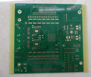
Solder mask or solder stop mask or solder resist is a thin lacquer-like layer of polymer that is usually applied to the copper traces of a printed circuit board (PCB) for protection against oxidation and to prevent solder bridges from forming between closely spaced solder pads. A solder bridge is an unintended electrical connection between two conductors by means of a small blob of solder. PCBs use solder masks to prevent this from happening. Solder mask is not always used for hand soldered assemblies, but is essential for mass-produced boards that are soldered automatically using reflow or solder bath techniques. Once applied, openings must be made in the solder mask wherever components are soldered, which is accomplished using photolithography.Solder mask is traditionally green but is now available in many colors.


Solder mask comes in different media depending upon the demands of the application. The lowest-cost solder mask is epoxy liquid that is silkscreened through the pattern onto the PCB. Other types are the liquid photoimageable solder mask (LPSM) inks and dry film photoimageable solder mask (DFSM). LPSM can be silkscreened or sprayed on the PCB, exposed to the pattern and developed to provide openings in the pattern for parts to be soldered to the copper pads. DFSM is vacuum laminated on the PCB then exposed and developed. All three processes go through a thermal cure of some type after the pattern is defined.


In electronic design automation, the solder mask is treated as a layer of the printed circuit board, and is described as a Gerber file like any other layer, such as the copper and silkscreen layers.


Available solder mask colors: Green, yellow, red, white, black, blue

 
Baggio WANG FAN
-----------------------------------------------------------
SHENZHEN JAAPSON TECHNOLOGY CO LTD
Building 2, Tongfuyu Industrial Park,Shenzhen, China, 518104
Tel: 86-755-82596922
Fax:86-755-82596922/82596923
skype: baggiowang0214
baggio.wang@funsunpcb.com
baggio@jaapson-pcb.com
www.jaapsonpcb.com

JAAPSON, The Expert in HDI Multi-layer PCBs

2015年7月13日星期一

Countersink Hole PCB


A countersink is a conical hole cut into a manufactured object, or the cutter used to cut such a hole. A common use is to allow the head of a countersunk bolt or screw, when placed in the hole, to sit flush with or below the surface of the surrounding material (by comparison, a counterbore makes a flat-bottomed hole that might be used with a socket-head cap screw).


A countersink may also be used to remove the burr left from a drilling or tapping operation thereby improving the finish of the product and removing any hazardous sharp edges.


The basic geometry of a countersink (cutter) inherently can be applied to the plunging applications described above (axial feed only) and also to other milling applications (sideways traversal). Therefore countersinks overlap in form, function, and sometimes name with chamfering end mills (endmills with angled tips). Regardless of the name given to the cutter, the surface being generated may be a conical chamfer (plunging applications) or a beveled corner for the intersection of two planes (traversing applications).


Baggio WANG FAN
-----------------------------------------------------------
SHENZHEN JAAPSON TECHNOLOGY CO LTD
Building 2, Tongfuyu Industrial Park,Shenzhen, China, 518104
Tel: 86-755-82596922
Fax:86-755-82596922/82596923
skype: baggiowang0214

JAAPSON, The Expert in HDI Multi-layer PCBs


2015年5月26日星期二

SHENZHEN JAAPSON PCB Manufacturer

Shenzhen Jaapson Technology Co., Ltd, which was founded in 2004, is a high-tech enterprise specializing in designing, developing, manufacturing and marketing of Printed Circuit Board (PCB). We introduced advanced production and test equipment from overseas, professional engineering& management personnel and state-of-art technique to make sure we provide our customers with PCBs of high quality, reasonable price, fast delivery time and timely after-sales.

Through our continuous efforts and improvement, we are able to fully meet customers’ requirement for multi-layer, MCPCB, HDI PCB and high frequency PCBs, either for samples or mass production. They are widely used in such fields as telecommunications, medical, power supplies, military, computers, industrial, automobiles, LED lighting, etc.

We gained great popularity because of our responsibility, effectiveness and quality. We have established good partnership with many famous international companies and have strong customer base in North America, Europe, Asia, including sales agents worldwide. Our factories pass ISO9001, ISO14001, and our products meet UL, RoHS standards.

Our Mission: Exceed customers' expectations and offer better PCB Solutions all the time!


Our advantages:
Jaapson PCB was established in 2004, we have 10 year’s experience
We passed ISO9001, ISO14001, RoHS certificates
70% of our customers are from Europe and North America
We use very good material, such as KB, Shengyi, Rogers, Taiyo solder mask..
100% of our prodcuts are tested and 100% pass
Free samples are available for your test
Some of customers includes: CREE, WAGO, OSRAM, PHILIPS, BYD
We attend dozens of Electronics Fairs in Germany, USA, HK, etc
Our production line works 24hours without any break, to ensure timely delivery
We are golden member of CPCA and SECC.


Baggio WANG
-----------------------------------------------------------
SHENZHEN JAAPSON TECHNOLOGY CO LTD
Building 2, Tongfuyu Industrial Park,Shenzhen, China, 518104
Tel: 86-755-82596922
Fax:86-755-82596922/82596923
skype: baggiowang0214